Show Posts

This section allows you to view all posts made by this member. Note that you can only see posts made in areas you currently have access to.


Messages - JRM

Pages: [1]
1
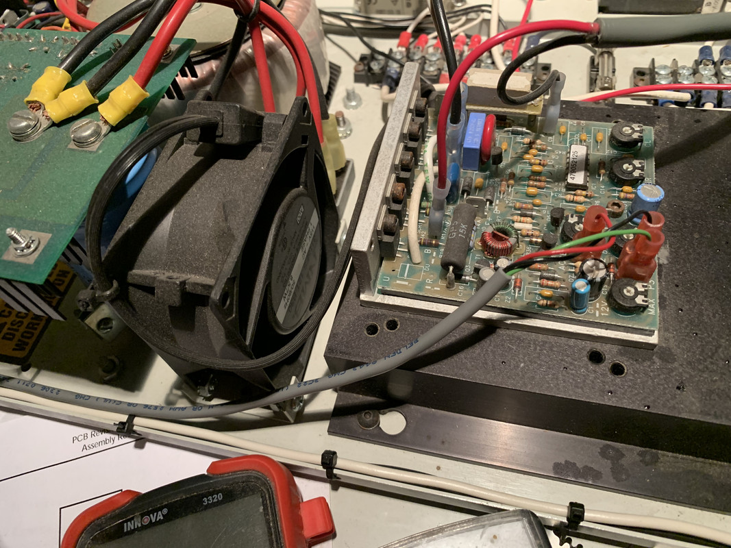
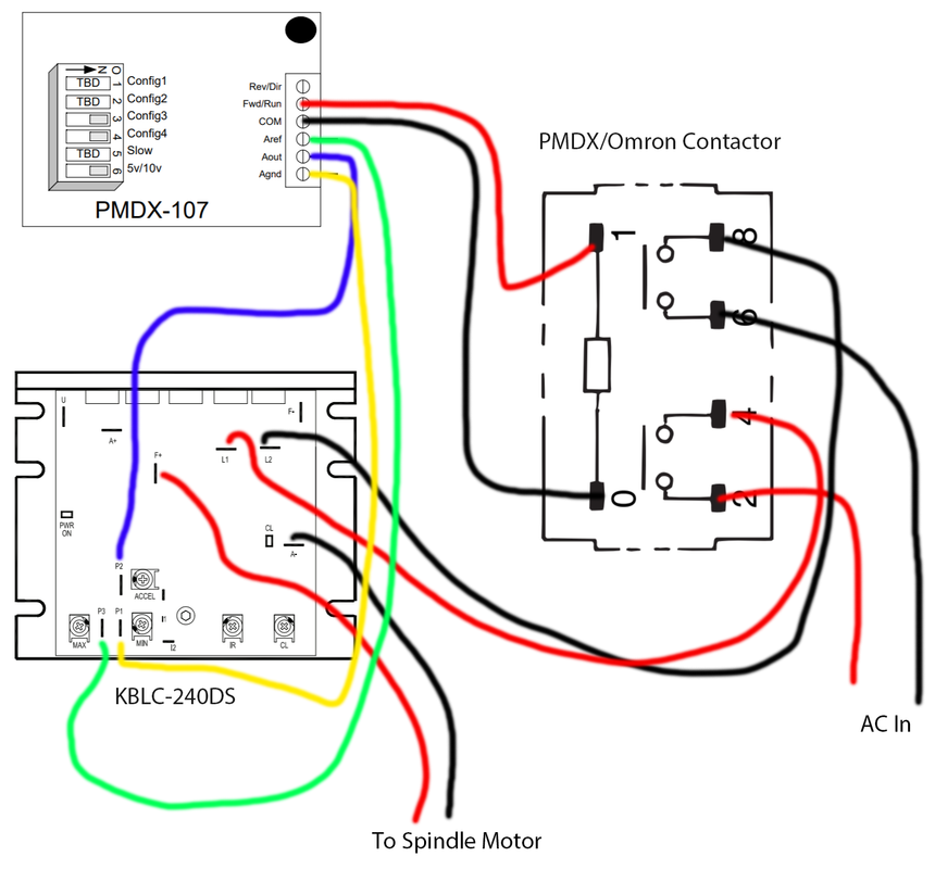
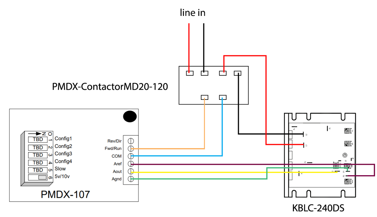
I tested between Aout and Agnd using two multimeters and didn't detect any voltage. I also tested both Multimeter using a 12V power supply and they are both detecting 12V I might test them on a 5V PC power supply later but neither of the multimeters are detecting any voltage between Aout to Agnd when I press the test button the first or second time. The spindle controller is wired as show in the diagram and this photo. The other photo was how it was wired using the original controller board.


2
The Contactor is working now based on how you explained to wire it. The diagram I posed is wrong though with how the spindle motor is connected it was never connected that way and always though A+/A-. When I started the retrofit this is how the motor control was wired.


When I run test mode the motor turns on when I press and hold the button, but when I press and hold the button a second time it seems to simply continue at the same spreed.

3
Below is the wiring diagram as I think it should be but the spindle doesn't turn on if its wired like this. I have 6, 4, 3 switched on. The contractor doesn't flip or seem to receive a signal from the controller to turn the KBIC-240DS on.


If I wire the KBIC-240DS directly then when I run test mode the spindle turns on and seems to run at full speed but changing the pot on the PMDX-107 doesn't seem to noticeable effect the speed. I also am not sure what the settings for the pots on the KBIC-240DS should be. The contractor still doesn't flip when its wired this way.


4
I have a PMDX-107 that doesn't seem to be sending anything to the J1 connector. All the lights flash like they should in test mode, but when I connected it to my motor control adjusting the pot doesn't change the motor speed. I am also using the Run/Com ports to flip a PMDX-ContactorMD20-120 on. I tested the PMDX-ContactorMD20-120 using 120v and it does flip but not when its connected to the PMDX-107. I checked between Run and Com using a multimeter and there isn't anything when its in test mode. I also checked between Aout and Agnd am I doing something wrong or is the board bad?

5
Ok that makes sense but I am not fully sure what PC ground is are you sure I should connect it to that and not just to the system ground? I saw someone else do a similar conversion but with a different breakout board and they just grounded it to the machines back panel. The four wires are for the interface cable that does step and direction there is a separate power connector.

6
I have a LabVolt 5600 which I am retrofitting I am trying to figure out how to connect the D&M Computing Chopper Driver.

There are four wires coming off the driver they are:

A yellow wire goes to a terminal on the driver labelled "D"
A grey wire goes to a terminal on the driver labelled "C"
A black wire goes to a terminal on the driver labelled "-"
A red wire with is goes to a terminal on the driver "+"

+ is 5VDC I am not sure how to connect the - wire should I connect that to the machine ground? I Think PCground wont be connected on this machine to anything since I am using a UC400ETH to connect to the pc. I think - might be the neutral side of a 5V circuit.


7
I am trying to connect a kblc-240 and the PMDX-ContactorMD20-120 is the diagram I made below correct?


Pages: [1]