Products for CNC and
motion control applications since 1998.
Design, manufacturing, and support based in the USA.
Click here to see what our customers say about PMDX
We save you money with our $13.00 flat rate Priority Mail shipping for most domestic orders.
General Information
FIND PRODUCTS:
Select Below
To Browse
- Listed by Number (All)
- PMDX-340 CNC Control Box
- Motion Controllers
- Breakout Boards
- Extra I/O & Isolation
- Power Sources
- Test & Development Tools
- Spindle Controllers
- Panels, Pendants & MPGs
- Contactors, Breakers,
SSRs & Power Switches - Noise Filters &
Common Mode Chokes - E-Stop & Control Switches
- Cables & Parallel Ports
- Connectors & Misc
- Software(Mach4,Mach3 etc.)
- Legacy Products
Our Most Popular Products
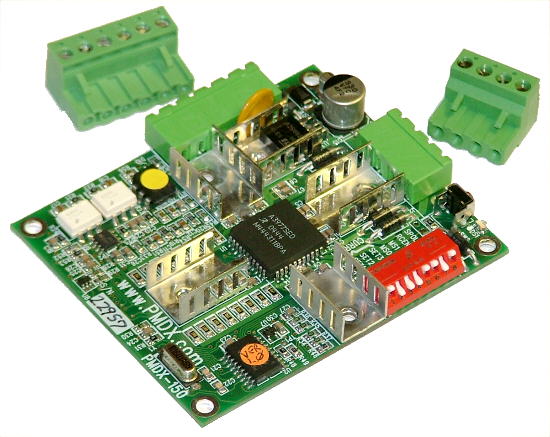
Model PMDX-150
Three Ampere Bipolar Micro-stepping Motor Driver
The PMDX-150 has now transitioned to legacy product status. It is still possible to special order them but they are not recommended for new designs. OEMs and those needing replacements should contact us via email for price and availability quotations.
Click on image for larger view
The PMDX-150 is a full featured, 3 ampere, bipolar stepper motor driver card.
- Based on the Allegro A3977 microstepping chip with a supporting microprocesser to add functions.
- Supports four micro-stepping and step multiplication modes.
- Dip switch current setting from 0.75 amperes to 3 amperes (with fan).
- Auto idle current reduction, with dip switch enable.
- Step pulse polarity is dip switch selectable.
- Opto-isolated inputs for step, direction, and output for fault.
- Step and direction are ground referenced and designed for easy drive from laptop or motherboard printer ports. The opto-isolators do not need a 5 volt power source.
- Single power supply voltage. Only the motor supply voltage is required. The logic supply voltage is internally derived.
- On board, self resetting power input fuse.
- Protection against reversed supply voltage.
- On board power supply filter capacitor, no external capacitor needed when using long power leads.
- Over-temperature shutdown and lockout. If the driver senses excessive thermal conditions it will turn off its output, pull the opto-isolated fault output to ground, and signal the fault by flashing the status LED. It is then necessary to cycle power or push the test button to clear the fault. This prevents the driver from cycling in and out of shutdown and makes sure that the operator knows to correct any erroneous motion before continuing.
- Overvoltage protection is provided for back EMF (returned energy from the motor) and from voltage spikes caused by loose wiring or unplugging motors with power on. Please note that this protection should not be relied upon to protect the driver from excess power supply input voltage.
- LED to indicate activity and fault conditions. Coded flash conditions indicate status or fault code.
- Push button test to run motor without computer and to reset fault conditions.
- The test button also forces a re-read of the DIP switches so that changed settings can be checked without cycling power.
- Separate pluggable terminal strips for power/control signals and the stepper motor.
- Mounting holes are provided on the board to allow installation of 45mm frame size fan directly on the board.
- The motor connector is designed to allow for mounting the driver directly against a panel with external access to plug in the motor cable without any additional wiring.
Download the full manual in PDF format here (revision 1.6, 776 KB).
Copyright 2004-2022